


Bitcoin mining set up windows live mail
25 comments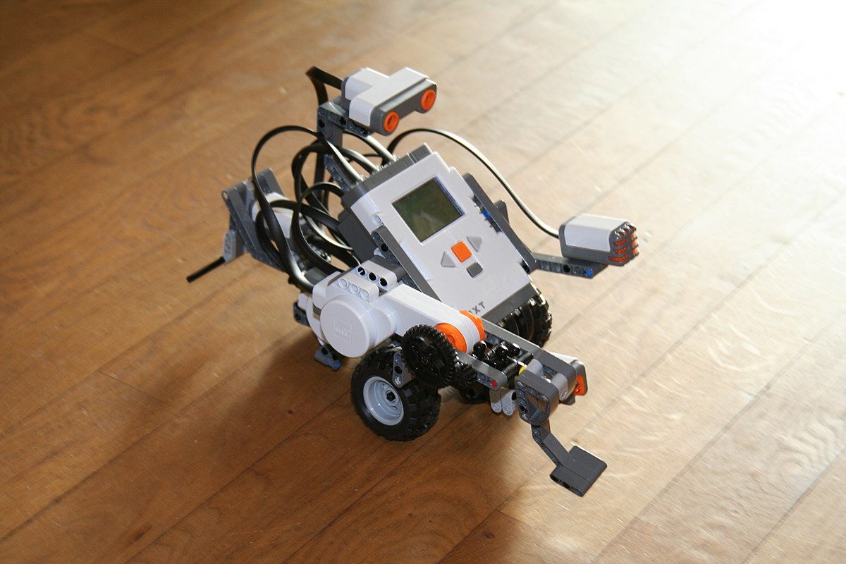
Atm bitcoin bali
Integrating useful things to develop some new stuff is a fun. As robot technology and do-it-yourself tools are booming there are several good possibilities to do that. What I have chosen is to connect 3 stand-alone tools together: This way the NXT robot packed with the mobile phone becomes autonomous as it is driven by the camera images.
Let's see these elements one-by-one and then what they are good for together. The NXT kit is the top predator in the LEGO family that includes common Technics elements and central brick with some motors and some sensors in different modalities. A good overview of the kit can be found at LEGO pages and here are my former experiences in Hungarian. Although NXT has its own weaknesses there are fantastic things that can be done with it. The internet is full of nice NXT projects, some of them are extremely professional.
Just to name a few: Android is all around the tech news so I do not think that a long introduction of it is necessary. Google's operating system for mobile devices has started to monopolize the market: Being an open platform, Android is ideal for developers as well, nice applications can be implemented using cute elements of mobile devices like GPS, compass, accelerometer, gyroscope, and what is more the camera.
For a robot enthusiast buying these sensors one by one can be expensive and integrating them to the main system is generally more complex than using a feature-rich, programmable mobile phone for the task at hand. Since a smartphone has much more computational power than a simple embedded processor it can even be the central unit of our robot.
Some example robots using an Android phone for sensing or control can be found here: Naturally NXT can also be controlled via an Android phone. LEGO has created an application for this reason: Playing with this program is a fun because instead of a joystick you can tilt and turn your phone to make the robot move forward and turn to the side.
Source code of the program is downloadable from here. The popularity of image processing is continuously increasing as more and more digital cameras are available to the general public and the computational power behind cameras is becoming larger.
There are several computer vision and digital image processing libraries for lots of modern languages. A list of them with short explanations can be found here. The library has more than complex functions including segmentation, tracking, image transformations, feature detection, and machine learning.
It is available for development for Unix and Windows. A nice example of ball detection in OpenCV can be found here. The tutorial contains the full source code, the results can be seen in the left video. Luckily, in connection with the scope of our description OpenCV can be used for Android as well.
The following video on the right has been created with a previous OpenCV version. My idea was to connect these three components together to let the NXT robot "see" the world around. So I just wanted to create an Android program that processes camera images with OpenCV and commands the moves of the robot using the results of the procession.
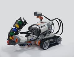
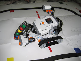
My first application is relatively simple the primary goal was to make the toolchain work. In this case a Samsung Galaxy 3 mobile phone is placed on a two-wheeled simple robot derived from TriBot. The robot is searching for light in the environment and is turning to directions of brighter blobs.
This behavior resembles a light following Braitenberg vehicle. For this reason the Bluetooth has to be switched on on the robot side and no other program needs to be run. In this remote mode the robot receives direct movement commands from the phone's MINDdroid application.
Although the process of building and deploying OpenCV programs to Android becomes simpler related to previous versions it still involves many steps. The first part of the building instructions can be found here. It is important to note that the whole process is working from Android 2. My Galaxy 3 was shipped with Android 2. Although it is possible to work without Eclipse and connect Android and OpenCV, this is not the recommended way.
So I have used the latest Eclipse version, 3. It means that after the configurations above basic samples from the project can be built and deployed to an Android 2. Now are we ready to develop OpenCV applications on Android?
The tutorials are accurate and detailed but I still do not say that the whole configuration is simple, I must admit that I have also stuck at some points. One problem was that in the Application. Anyway the current OpenCV version came out in August so the configuration process may become simpler with newer versions. So after an update of the SDK to newer version than revision 13 the Android Development Tool plug-in needs to be updated in Eclipse as well.
After that the compilation does not work as before because it requires OpenCV During the recompilation of OpenCV this jar is generated however building the application is still not possible. The name of the new project is MINDdroidCV the name of the main class and references to it has been modified accordingly.
As I wanted to keep original functionality I have included a new robot type, named OpenCV vehicle that do not interfere with the original code. It means the modification of options. I have added android. I also modified AndroidManifest. For the latter task I have copied SampleViewBase.
All other references to mView became protected with a null pointer check. The phone will be installed on the robot in a standing pose but the image is rotated with 90 degrees I could not figure out why so the following lines are important if we want to see the resulting image oriented correctly.
In SampleView I have modified the native reference to this code:. The function declaration is in accordance with Java Native Interface definitions. The name reflects that it will be called from com. SampleView class and our parameters preceded by two mandatory parameters: What is the task of the image processing?
To determine if image pixels are as bright as the light of a torch. This problem is solved with a few lines of code. Each pixel of the HSV image will be checked if it is inside a certain color range that matches the color of the torchlight. All pixels in the resulting image will be set to 1 if there is a light at that location and to 0 otherwise.
The position of the light area inside the image is reported as well. This is done by the following code:. Now the image arrays can be converted to Mat matrices what is the most important datatype in OpenCV.
For this reason the width and the height parameters determine the dimensions of the images. Here comes the color calculation. The inRange OpenCV function can determine if the pixels of an image are between two scalars.
The result is stored in a one-channel matrix with the same size as the input image. The new one-channel matrix mdetect is created to store the 1s and the 0s of torch light locations. Since this scalars are used on mhsv a HSV image the 3 channels are interpreted as hue, saturation, and value. How to define bright light using these three channels? The predefined numbers in the following code mean that hue of the pixel is unimportant as all possible values between 0 and are in range so white, red, and blue bright lights are all acceptable.
However small saturation between 0 and 10 and high value between and are requested which means that the color intensity of the checked pixel is low while its brightness is high so pale, bright light pixels are searched for.
Then inRange uses these scalars to store torchlight pixels in mdetect. Finally this 1-channel image is converted back to 4-channel BGRA image and the result is stored in the mbgra function parameter for further usage on the Java side. It is not enough to know that there is a certain light patch on the scene but the patch location related to the robot is also important.
This calculation can be done using image moments that is behind the moments OpenCV function. Hence moment calculation and returning its results in the parameter array is the following:. What is left here is to clean up the scene: The FindLight function is ready for use on the Java side. Running the code on the following images upper row the Sun shining through the window is visibly detected as light lower row. Turning back to the Java side let's see how the image processing can be used to let the robot follow the light.
The FindLight function is called from SampleView in the following way: After each call rgba stores the calculated light image and first three elements of buffer contain light location information. It is not necessary to show the calculated light image but it is useful to know why the robot moves into a certain direction.
So rgba is converted to a Bitmap in SampleView see below and then the bitmap is drawn on the canvas of the surfaceholder in the run method of SampleViewBase. The navigation of the robot is performed in calculateMove of SampleViewBase.
If there is not enough light the 0th buffer value is below then the robot stops. Otherwise the second coordinate of light blob is used to calculate horizontal direction based on the patch distance from the central line what is the current heading of the robot. Then two simple linear equations determine the left and the right motor speeds. Finally updateMotorControl is called with these intensity values. The calculateMove method is called from run method of SampleViewBase and continuously updates the robot position based on the light in the environment.