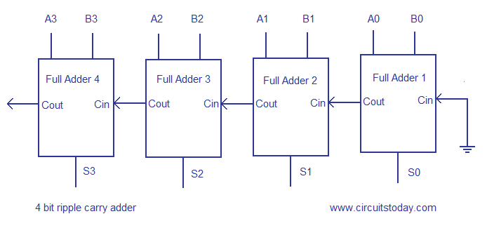
4 bit ripple carry adder layout background
Using only two types of gates is convenient if the circuit is being implemented using simple IC chips which contain only one gate type per chip. Some other multi-bit adder architectures break the adder into blocks. Assumed that an XOR-gate takes 1 delays to complete, the delay imposed by the critical path of a full adder is equal to.
It is possible to vary the length of these blocks based on the propagation delay of the circuits to optimize computation time. This can be used at multiple levels to make even larger adders. To reduce the computation time, engineers devised faster ways to add two binary numbers by using carry-lookahead adders CLA. The sum and the carry may be fed into two inputs of the subsequent 3-number adder without having to wait for propagation of a carry signal.

If the addends are four or more, more than one layer of compressors is necessary, and there are various possible design for the circuit: 4 bit ripple carry adder layout background circuit produces a two-bit output. The gate delay can easily be calculated by inspection of the full adder circuit. This kind of circuit is most notably used in multipliers, which is why these circuits are also known as Dadda and Wallace multipliers. In most cases, P is simply the sum output of a half adder and G is the carry output of the same adder.
![]()
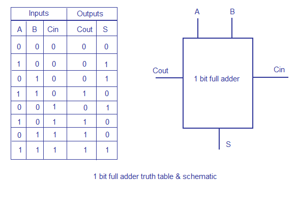
The output variables are the sum and carry. If an adding circuit is to compute the sum of three or more numbers, it can be advantageous to not propagate the carry result. By combining multiple carry-lookahead adders, even larger adders can be created.
The sum and the carry may be fed into two inputs of the subsequent 3-number adder without having to wait for propagation of a carry signal. In this implementation, the final OR gate before the carry-out output may be replaced by an XOR gate without altering the resulting logic. It has two outputs, sum S and carry C.