

Bitcoin slides on sec crypto exchange crackdown fears and binance hack rumour
28 comments
Bitcoin mining ubuntu gui programming
Programming a Line Follower Robot is the next step that you should do after building it. This is a follow-up on my previous post Line Follower Robot - Build it from scratch. You have to calibrate the code to work properly with the hardware you have built. So the first step in programming is to make a demo track. This will help you test your code then and there. Here is the track that I built for my line follower.
The line is little over 3. I used a black chart paper to make the track and stuck it over white one. You can come up with you own innovative ideas but this is the most straight forward method I can think of.
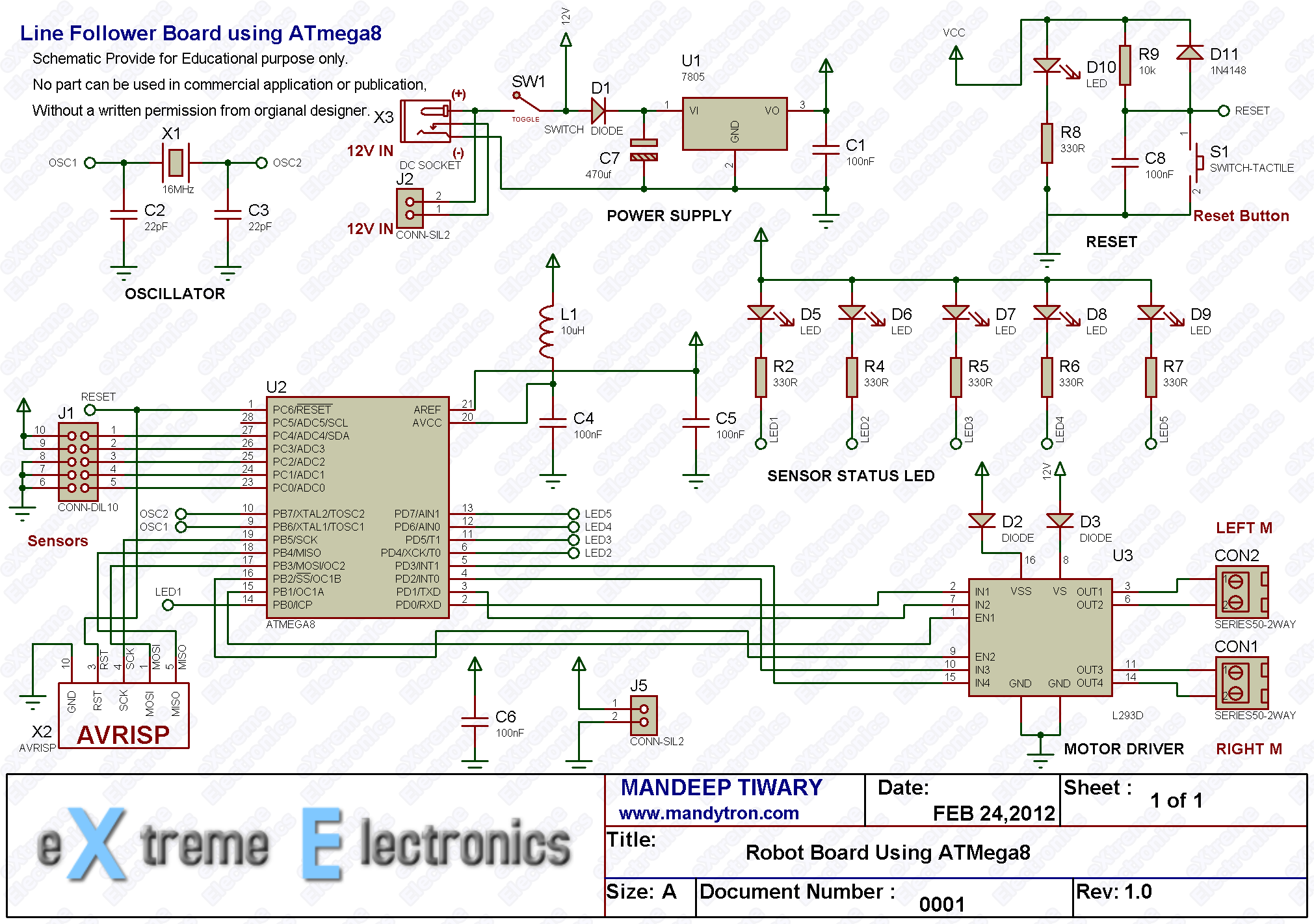
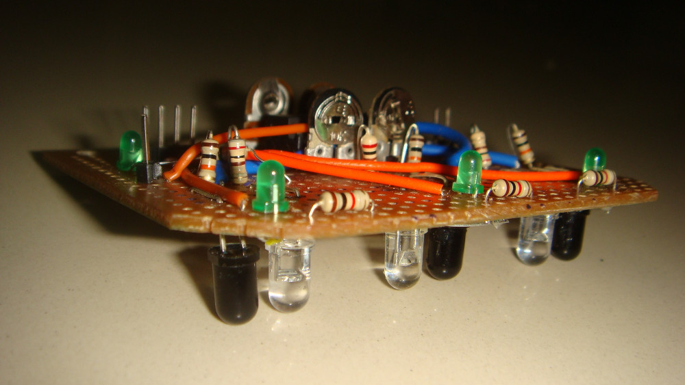
If you have a better idea leave a comment. The next step is to sit with a pen and paper and make reading from the track that you just made. If you had used the circuit diagram that I posted or something similar, you should be having some indication LEDs at the output of the comparators like this one here,.
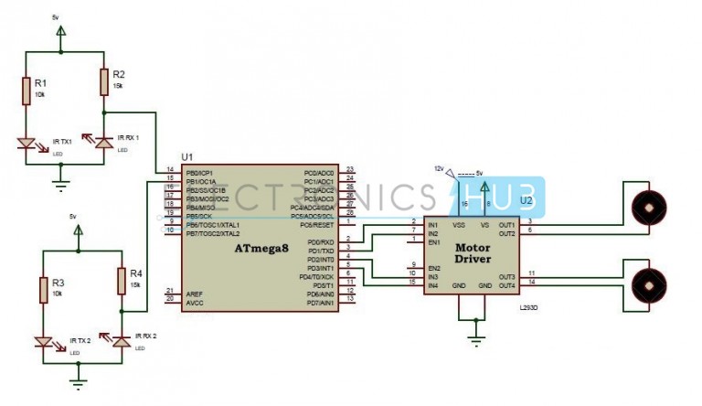
I placed the output LEDs green directly above the line sensor to avoid confusion. This made my board look really bad. Again was a trade-off between the look and the feature, I choose the feature. It is really helpful if those LEDs are right on top of the sensors. The IR emitter emits a constant IR beam. The white surface reflects most of the beam while the black surface absorbs most of the beam. This reflected beam is picked up by the IR detector and its conduction increases and hence a voltage variation in the output pin 0v for absence of IR rays and 5V for maximum intensity.
This is given to the comparator to compare with a reference signal generated by the potentiometer. That is how the line is sensed by the sensors. Back to the post, you have to place the bot over the line and see what it reads for various position of the line. Make sure that the line is always detected at least by one sensor if it is within the range of the three sensors. This is something for which you should take utmost care. I even mentioned in my previous post the maximum distance between the sensors should not exceed the width of the line.
With the calibration values at hand, you can start programming your robot. In your while 1 loop you should have a series of if statements which polls of these calibrated condition and makes direction changes accordingly.
The red dots are the sensors that are just above the black line and the green ones are on the white background. Case 1 is when the robot has to move forward as only the center sensor is low. Similarly Case 2 is towards right, Case 3 is towards left and case 4 is stop as all the sensors read high.
This code should be good for any linear track with normal bends. But this is not going to work if your track has right and acute angle turns. That is when we have to add some more logic to the existing one. Say you are facing a right angle, what would your sensor data read? The center sensor along with either of the two side sensors will read LOW.
This is when you have to tweak the direction logic a little. Now you have to define two kinds of left turns. One of it will rotate your right motor forward and the left motor backward. Do the same thing with the right turn logic. Now your code should have these lines too,.
You might have to survive a finite discontinuity in track or detect patterns in track to do some other tasks such as glowing an LED or setting up an alarm in the buzzer. Some of them even have inversion in logic you will be asked to follow white line on black background all of a sudden: This is just the beginning of line follower robot. There are a lot of possible difficulties that can be set up for you in a contest.
All cannot be discussed here. But we will discuss some of the most common one listed above in the posts to come. We will specially give importance to the Shortest Path solving robot in the near future.
Your robot has to go from the source to the destination by traveling any distance but return to the source from the destination but the shortest path only.
Siddharth is the founder and editor of embedjournal. He is a Firmware Engineer, techie, and a movie-buff. You get to know him on the following social channels. Programming a Line Follower Robot Jun Serial Ports are dead?