Digital Counters
4 stars based on
75 reviews
A counter is a sequential logic circuit that goes through a prescribed sequence of states upon the application of input pulses. The prescribed sequence can be a binary sequence or any other sequence. A counter that goes through 2 N N is the number of flip-flops in the series states is called a binary counter.
2 bit ripple counter truth table modulus of a counter is the number of different states it is allowed to have. Counters are very widely used in almost all computers and other digital electronic systems. There are two major 2 bit ripple counter truth table of counters: Counters arranged so that the output of one flip-flop generates the clock input of the next higher stage are generally called asynchronous counters or ripple counter.
In other words, in asynchronous counters, the CLK inputs of all flip-flops except the first one are triggered not by the incoming pulses but rather by the transition that occurs in other flip-flops.
Therefore, the change of state of a particular flip-flop is dependent upon the present state of other flip-flops. When a transition from, say, to occurs, the one-to-zero transition of the low-order three bits ripples from bit to bit. Since each flip-flop has a non-zero propagation delay, ripple counters are relatively slow. Therefore, an upper limit on the number of flip-flops in the flip-flop chain ought to be imposed. Synchronous counters eliminate the 2 bit ripple counter truth table flip-flop delay seen in ripple counter.
Each flip-flop is clocked by the same clock signal. Each gate selectively controls when each more significant bit flip-flop is to change state toggle on the next clock transition. Such control enable can be realized by setting, 2 bit ripple counter truth table example, the J and K inputs of a J-K flip-flop. Because of this control, the addition of a common clock will synchronize data transfer and all flip-flops will change state simultaneously. The important feature of a synchronous counter is that the transitions of the individual flip-flops are synchronized to a master clock signal.
J-K flip-flops are normally used in the synchronous counters due to the enabling controlling feature of the J and K inputs. There are two basic schemes for generating the J and K inputs. One of them is illustrated in the four-bit binary counter shown in Fig. Notice that the information to the J-K inputs is formed in a parallel fashion.
The counter is accordingly termed as synchronous parallel counter. In the parallel scheme the number of inputs to each AND gate increases linearly with the number of stages. For this added expense one gets the fastest possible synchronous counting circuit. If the J-K input information is formed from the output of the AND gate in the previous stage, one has a synchronous serial counter. Although the serial scheme is slower than the parallel scheme, the number of inputs to the AND gate per stage is constant in the serial case two inputs per stage.
Connect the count-up ripple counter shown in Fig. Set data switch SW1 from logic 0 to logic 1 clear all flip-flops. Now connect CLK to a pulse generator in your pencil box J-K flip-flops in 74LS76 are negative edge triggered and start counting by pushing the pulser button.
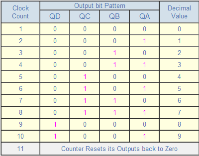
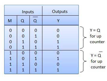
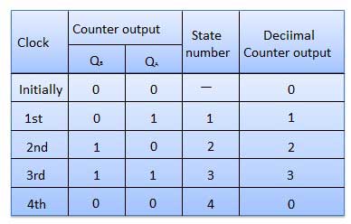
Continue the process and record the output of each transition in a truth table. Does it count correctly? We can convert the count-up ripple counter to a count-down ripple counter by connecting the clock of the flip-flops to Q instead of Q the LEDs are still connected to Q. Make the modification and try out the circuit. Connect the 4-bit synchronous parallel counter as shown in Fig.
Repeat the same procedures in the ripple counter experiment. From the transition table of the counter and the excitation table of the J-K flip flop, verify that the J-K inputs to the flip flops are correct. Estimate the highest possible clock frequency for 2 bit ripple counter truth table 4-bit counters in this experiment with the data supplied by the Data Book.
Introduction A counter is a sequential logic circuit that goes through a prescribed sequence of states upon the application of input pulses. Asynchronous Counters Counters arranged so that the output of one flip-flop generates the clock input of the next higher stage 2 bit ripple counter truth table generally called asynchronous counters or ripple counter.