Ripple Carry Adder Module in VHDL and Verilog
5 stars based on
70 reviews
Adder Verilog Are you looking for?: Verilog Hardware description language. Hi, Design a two stage pipeline 16 bits adder with verilog code, assume you can use the 8 bit adder macro module. The input and output signals are defined as: Is the prefix sum operator synthesizable in verilog??
It may be desirable to pipeline the design, or to share adder resources. I assume this is some sort of school example? You'll have to write the full and half adder blocks.
6 bit ripple carry adder verilog code examples instantiate them and connect them all yourself - one of the most basic things of verilog.
Plenty of examples out there I guess not much. It also depends on the logic implemented in the FPGA. Vivado has understanding of the device it is compiling the code for. So it probably has taken the best optimization already.
And remember; synthesis tools are better at optimizing than you are. Net has unmapped pin s. Hello, I'm trying to synthesize an adder.
During synthesis, RTL compiler informed "Net has unmapped pin". However, synthesis still succeeded. Then I checked the mapped netlist file.
Surprisingly, there was no unmapped pins? Hello everyone, I am trying to design 32 bit binary signed digit adder but I am facing issue while writing code for signed number. The logic does not match a known FF or Latch template. I'm trying to implement only the functionality of the 8-bit adder using an always block.
Instiating submodules in verilog. Dear all I am new to verilog. I have written the below code for full 6 bit ripple carry adder verilog code examples using two half adder s. The code for half adder is given at the end. Please help me in this regard.
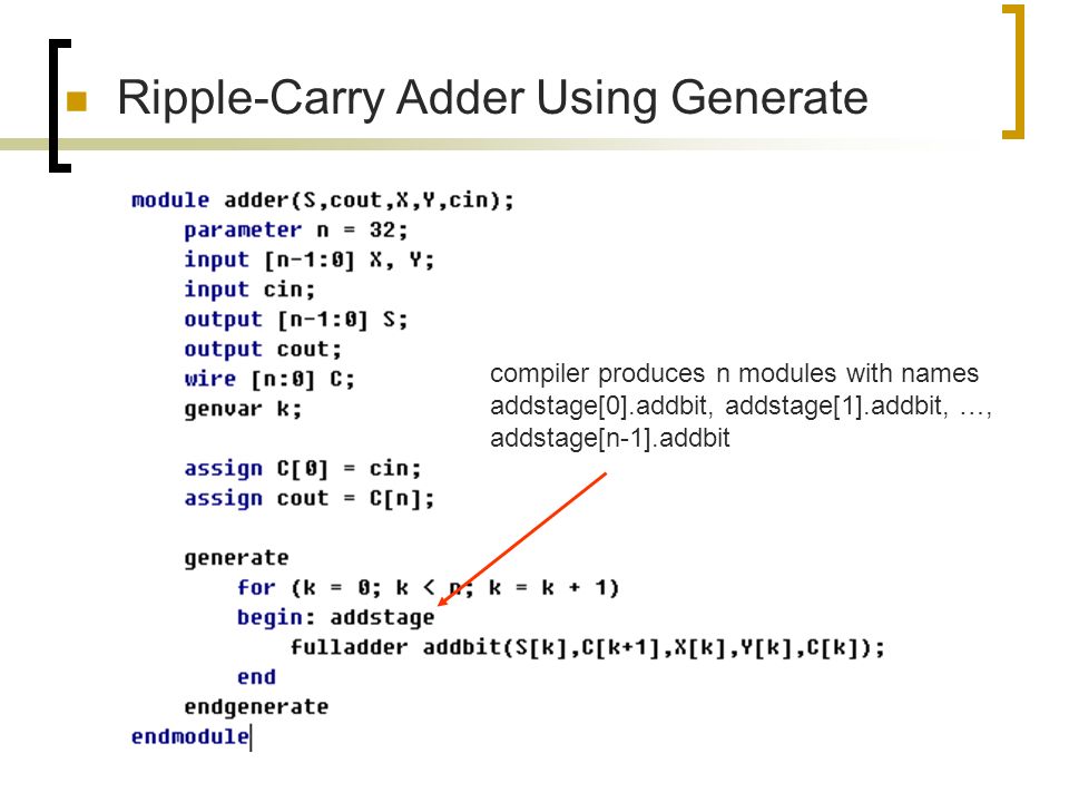
Group 1bit Adders in Design Compiler. I have a design which requires 32bit adder s, I have made a 1bit full adderand used generate statement in verilog to make it 32bit adder. Will grouping these 1bit adder s together in Design Compiler help in optimization or should I just leave them as is? How to call a verilog module from another source. There is no concept of "calling modules". You can instantiate the full adder module in source2 and access the ports of the full adder module in source2.
I am doing addition of "A" and "B" in an adder design,where A and B both are 8 bits each, and I want to know how much resources are utilized in terms of Slices, etc in Xilinx for different simulations. Can I get the count in Xilinx? Need help with 8bits accumulator using 4bits adder.
I need to construct an 8-bit accumulator. For this, I need an 8-bit adder. But my ASIC 6 bit ripple carry adder verilog code examples So I construct the accumulator. When I synthesized the circuit, I found that there was a max-delay violation on the? To correct this, I added a flip flop in Can anyone look into the code and suggest corrections? This circuit definitely has to be clocked.
Else the tool reports it as a combi loop. You can have a 2: The flop must be in the path from the output to back to Cin while the adder should be combinational logic.
ALU that multiplies using asterix-Verilog. It's because you implemented your 6 bit ripple carry adder verilog code examples adder as a structural implementation How to deal with simulation with too many pins? Hi everyone, I have a question when I want to simulate a simple adder by cadence virtuoso. I've designed a bit adder and would like to make a simulation. But it seems too boring when I do so because there are almost pins. How N-stage 4-bit Adder logic synthesis in Design Compiler.
Now I need elaborate the design, don't know what type of adder is? Can any tell me what type of adder come out from Synopsys Design Compiler.
I am new to this forum as well as to verilog!! I wrote a code for the multiplication of two 8 bit numbers using shift operator and adder Modular 8 bit Ripple Carry Adder Help! I am trying to build a ripple carry adder using a hierarchical verilog structure description.
What I have is not working right My logic is messed up somewhere but not sure where. I grabbed the test bench from a 8 bit multiplier to use for the RCA and so I know I am overlooking something basic I need to make a 6 bit full adder using verilog Xilinx. And I need to use a 4 bit adder and two 1 bit adder s. Can you guys please help me? This is how I start: If you have full adder then you have HiIs it possible to use clock gating in combinational circuits like full addermultiplier etc.
Pls give me the design or verilog code? Help, Verilog code for frequency "adder and substractor". Hello, im new to verilog and i need your help. What i mean is this: I need a code with for example input A, and input B If I have a 1K clock inputI can divide its frequency to for example hz.
Then the my code has to do this: Triggering a Combinational Logic module from a Sequential Logic module. I am having a separate module for the 4 bit ripple carry adder. I have tested the adder module and it works fine.
I dont see any advantage using system verilog to test an adder. If you don't need an encoded 6 bit ripple carry adder verilog code examples, this. Gererate netlist with Verilog-A. I want to take one cell with a schematic view from my library and place it N times in a row in series. For example that could be a N-bit adder which is composed by 1bit cells. Can I do that in verilog -a using a for loop or something similar? Is there any other way? I repeat that the original cell has only a schematic view a.
Software Problems, Hints and Reviews:: Can you please be more specific? I looked up fixed point in google and didn't find any good source. Can you recommend a good source or help me with a basic fixed point adder? I tried to understand this but as it said my simulator just gave me integers. I'm writing the verilog code for radix selection unit. Extend the four-bit ripple carry adder to 16 bits using four of the four bit adders. Need a verilog structural code for Extend the four-bit ripple carry adder to 16 bits using four of the four bit adder s.
Verilog Weird Error with logical 6 bit ripple carry adder verilog code examples code but has errors in compilation. I got an assignment for my university. I made that code: