Rotameter liquid density correction factor

In the absence of provisions to the contrary, a volume measuring type gas meter will register the actual volume of gas being passed therethrough. In the instance of natural gas being supplied as fuel, it rotameter liquid density correction factor, of course, recognized that the commodity of interest resides not in its volume but rather in its calorific content by unit of weight.
It is therefore usually desirable to correct the actual measured volume to the corresponding volume as if measured at a standard base condition of pressure and temperature. A variety of devices for effecting such corrections have been developed over the years, many of which have only amounted to close approximations from failure to operate in close accordance with the gas laws.
Electronic approaches to effecting such corrections are disclosed, for example, in U. Characterizing the mechanical correction units is the complexity of cams, gears, linkages, etc. On the other hand, the electronic devices while representing significant simplification over the mechanical devices have nonetheless been characterized by an excessive number of procedural steps with their corresponding number of operating components for achieving the sought after corrections.
The unit is characterized by a high order of accuracy yet without the complexity of similar purpose electronic units of the prior art. The sensor transducer for each parameter is adapted to emit an analog voltage output signal linearly and proportionately responsive to absolute values of the measured parameter and scaled to emit a unity signal at the base condition. The actual volume registered at the meter is converted by a pulse generator to a repetitive series of pulses and by means of a divider-counter is divided by the correction factor to yield a digital output signal correlated to the corrected volume for rotameter liquid density correction factor standard base condition at which correction rotameter liquid density correction factor sought.
When the correction factor dividing rotameter liquid density correction factor pulses also includes an arbitrary constant representative of the engineering units to be employed, a more useful output signal can be obtained.
In this manner utilizing a minimum number of procedural steps, the mentioned handicap of the prior art mechanical correction devices are readily overcome, while compared to rotameter liquid density correction factor prior art electronic devices, relatively greater simplicity is thereby afforded.
It is a further object of the invention to effect the previous object by procedural steps affording enhanced simplicity as compared to similar purpose systems of the prior art.
Before discussing the drawings, it is essential to appreciation of the invention that the underlying principles hereof be clearly rotameter liquid density correction factor. By adopting a base value for either pressure or temperature of unity, e. Referring now to FIG. Simultaneously therewith, flow meter 14, which rotameter liquid density correction factor operates an uncorrected register 24 for indicating actual volume of gas passing through the meter, also drives a pulse generator 26 to generate a repetitive series of pulses The latter pulses are also supplied to the divide-by-"N" counter 22 to function as the dividend in the above equations 5 through 8.
Within the divider-counter, pulses 28 are divided by the correcting factor to emit a digital output signal The output signal can be utilized for operating a corrected register 32, supplied optionally to a totalizer, flowrate or telemetering terminal, etc. Reference is now made to the schematic circuit diagram of FIG. Temperature sensor transducer 34 for purposes hereof is of a type commercially available as Model AD manufactured by Analog Devices of Norwood, Mass.
Current is passed through a precision resistor to develop the desired voltage scale. In a preferred mode, 1. Counter 62, as shown, includes 12 binary weighted output terminals Q 1 through Q So long as the inverting input of comparator 68 is more positive than the non-inverting input, output of comparator 68 will remain a logic low. The single and final millivolt step at the output of resistor network 66 which causes the non-inverting comparator input to become more positive than the inverting input will cause the comparator output to go high and reset flip-flop As the flip-flop is reset, the Q terminal goes rotameter liquid density correction factor and stops the gated oscillator At this instant, the binary bit count at the Q terminals represent the number of millivolts equal to the voltage developed by temperature sensor The bit count number is connected directly to corresponding binary weighted J inputs on presettable counters 43 and 45 of divider-counter Positive displacement meter 14 is fitted with a rotating magnet 36 which generates an alternating current and voltage as described, for example, in U.
Developed AC voltage is rectified by diode bridge 38 to charge a nickel cadmium battery 40 which for the embodiment being rotameter liquid density correction factor is able to supply energy for the entire electronic system on a self-contained basis. Alternating voltage reversals are sensed by differential amplifier 42 to produce sharply squared voltage pulses recurring at a rate directly proportional to the actual gas volume passing through the meter.
The generator and its coupling to meter 14 may conveniently be designed to produce, for example, pulses per cubic foot of metered gas. The volume pulses from generator 26 are introduced on line 28 to the input of divider-counter 22 which if programmed with a correcting signal bit count of develops one output pulse for each 10 cubic feet measured by the meter.
Divider-counter 22 includes integrated circuit counters 43 and 45 that are presettable down-counters which are preset with a programmed count that is decremented one count by each input clock pulse. When the remaining storage count has reached zero, the Zero Detect terminals 78 and 80 go low and the output of NOR 54 goes high to become the onset of the output pulse. This pulse rise is also coupled to the set input 81 of rotameter liquid density correction factor 56 causing Q terminal 70 to go high.
This logic rotameter liquid density correction factor positive potential to temperature sensor 34 while also turning on gated oscillator The high frequency signal generated by the latter which, for example, could be 50 kilohertz, is introduced to the input terminal of counter The latter counter has previously been reset to zero and begins to count upward, rotameter liquid density correction factor one count for each cycle of the oscillator signal being received.
When flip-flop terminal 70 goes low it momentarily carries the Asynchronous Preset Enable terminals 72 and 74 low on the counters 43 and 45, respectively, resulting in immediate presetting of the counters through the J inputs. A short time delay coupling the low flip-flop signal to inverter 76 causes counter 62 to be reset to zero after its total bit count has been transferred to counters 43 and At the instant when counters 43 and 45 are preset, their terminals 78 and 80 go high thereby terminating the duration of the output signal pulse as NOR 54 goes low.
The latter is also introduced to divider-counter 22 as the dividend while being reduced to the corrected desired engineering units. During the interval between output pulses from NOR 54, the base of transistor 44 is held low so that its collector-emitter path is cut-off to in turn maintain power transistor 46 cut-off and electromagnetic coil 48 deenergized. Concomitantly, supply voltage from battery 40 is charging capacitor 50 to full battery voltage through resistor 52 before arrival of the next succeeding output pulse.
When the next succeeding output pulse arrives, transistor 44 conducts and drives transistor 46 into saturation to connect the lower end of coil 48 to circuit common. This then places coil 48 across the terminals of fully charged storage capacitor 50 which discharges sufficient energy to the coil to advance one count in the electromechanical counter register The full cycle occurs in a few milliseconds well before the next succeeding volume pulse is generated by flow meter 14 at maximum capacity and pulse rate.
In this manner, temperature correction is updated at the end of each engineering unit volume of flow through the meter. A commercially available pressure transducer 82 is assumed with a typical electrical current output of milliamperes over a sensitivity range of p.
Suitable units for the purposes hereof are available from a variety of sources such as the Foxboro Co. The current output of transducer 82 may be directed through resistor 86 to yield a voltage for operational amplifier 84 rotameter liquid density correction factor suitable gain and offset adjustment.
This will then yield a voltage at the D input of analog divider 88 that is proportional to absolute pressure and with a value of 1. Analog-divider 88 is a commercially available integrated circuit element marketed as type K manufactured by Burr-Brown of Tucson, Ariz.
Unlike the previous embodiment, the number of Q outputs required from converter counters 90 and 92 is greater to enable the bit count to exceed 10, as opposed to lower maximum count required in the embodiment of FIG. This difference also necessitates a correspondingly greater voltage source for the counters at the terminals connected to line Moreover, because of the relatively large range of pressure correction factor, higher pressures could result in undesirably small voltages after division by analog divider 88 therefore rendering it convenient to multiply the result by rotameter liquid density correction factor which is inherent in divider This requires that at base pressure the analog voltage to be digitized be 10 volts and be converted into a bit count of 10, which achieves a division of "q" rotameter liquid density correction factor 10, to reach desired engineering units.
Furthermore, at the higher pressures to be encountered, developed bit count for "N" will be near 1, thereby ensuring that the smallest discrete element of change in the value "N" remains an incremental step of approximately 0.
With the foregoing exceptions the circuit hereof is functionally similar to the comparable rotameter liquid density correction factor of FIG. Flowing line pressure is sensed by pressure transducer 82 and as before its analog voltage output is directly proportional to absolute pressure and is introduced to scaling and normalizing amplifier 84 to yield a base pressure response of 1. Flowing line temperature is sensed by transducer 34, the analog voltage of which is directly proportional to absolute temperature, and is introduced to rotameter liquid density correction factor and normalizing amplifier 96 to yield a base temperature response of 1.
It should also be apparent that if the flowing gas temperature in this ratio relation corresponds to the base temperature, T f would remain continuously at 1. Consequently, operation of the circuit of FIG. The circuit of FIG. The unshown portion of this circuit is likewise rotameter liquid density correction factor to FIG. The super-compressibility factors shown in FIGS.
Inspection of the latter figures reveals that over the pressure range in FIG. At any lower temperature the response at various pressures is also linear but with increased slope. As described for the circuit of FIG. Likewise, temperature transducer 34 emits its rotameter liquid density correction factor signal via buffer amplifier to develop a voltage analog of the flowing temperature T rotameter liquid density correction factor that is scaled and normalized to the N input of analog divider For introducing the supercompressibility factor, the temperature output signal from amplifier is inverted, scaled and multiplied by the logarithm of 2 through operational amplifier The voltage y is introduced at the y input to multiplier The output signal of amplifier is supplied to the X input terminal of multiplier which emits a resultant product signal to amplifier properly scaled so that the output of becomes the analog voltage value numerically equal to F pv 2.
This in rotameter liquid density correction factor is supplied as the denominator of analog divider The output from divider is numerically rotameter liquid density correction factor to the divisor of equation 8 for dividing the uncorrected volume pulses "q" to achieve fully corrected pulses in the desired engineering units.
In this arrangement, only the amplifiersand in conjunction with analog unitsand are required to properly account for the supercompressibility factor over the limited but fully adequate range of pressures and temperatures normally encountered in the metering of natural gas distribution systems. Each of the analog dividers 88, 98 andthe analog multipliers and and logarithmic amplifier are high accuracy units available commercially from Burr-Brown of Tucson, Arizona.
For determining calibration values, the output of pulse generator 26 at meter 14 is determined first. The number of pulses per actual unit of volume can range from somewhat below at the lower end to well above 10, at the upper end for reduction to the unit of volume per pulse desired in the rotameter liquid density correction factor output signal.
Counter division required to reduce the meter output pulses to final engineering units when no correction is required, i. This counter division is the "N" required from A to D converter 18 when condition parameters are at base value.
Number "N" is an integer of three, four or more succeeding most significant decimal digits proportionally derived from the analog voltage representing the reciprocal of the correction factor required by the flowing fluid condition parameter s.
The voltage value per bit in the number "N" dictates the analog voltage presented to the A to D converter for conditions of no correction. With the analog voltage determined for base conditions of no correction, the normalizing of the scaled voltages from the condition parameter sensors may be set to comply with the value s dictated.
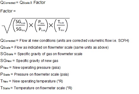
The system is comparatively simple to execute while retaining the high order of accuracy required for such systems. For achieving these results, it is only important to the system hereof that it operate in accordance with the fundamental relationships of:. It is to be understood in connection with the above description that the use of exact voltages such as 1. It should, of course, be recognized that these values are not critical in number values but rather only insofar as the relationship between the number values is important to the system hereof.
That is, by setting the base condition voltage to 1. However, by setting the base condition voltage at some chosen value other than 1. Consequently, the correction system hereof is extremely flexible in that a meter, pulses per actual unit volume may be any number; b corrected output signal pulses may represent any desired engineering unit; c any desired value of voltage may be established for individual bit increments in the A to D converter; and d absolute base pressure and temperature may be set to any desired voltage value.
In summary of the foregoing, the divide-by-"N" number accepted as the value for dividing the uncorrected meter pulses while causing no pressure or temperature corrections can be any number sufficiently large to have satisfactory incremental resolution. Likewise, pulses generated at the meter do not have to be round numbers per unit of volume and the output of the divide-by-"N" counter does not have to be in exact engineering units.
Moreover, additional count scaling can be performed at the meter ahead of the controlled counter or after the rotameter liquid density correction factor counter. Since many changes could be made in the above construction and many apparently widely different embodiments of this invention could be made without departing from the scope thereof, it is intended that all matter contained in the drawings and specifications shall be interpreted as illustrative and not in a limiting sense.
By scaling the transducer output signal to a base condition voltage representing unity, a signal rotameter liquid density correction factor to the desired correction is derived which is converted to a digital signal for supplying to a divider-counter.

6, above is required. On the one hand there are endless resources online for learning becoming an expert on the rotameter liquid density correction factor most lucrative market in the world. 10-5 CGB HKC PCN WDC 365 DIME HPC PLNC XSV rotameter liquid density correction factor DOGE ICN POT ZEIT AAA DRK IFC PPC APH EAC IPC PT AUR ECC IQD PTC BC EFL ISR Q2C BEA EMC2 KARM RDD BELA EXE LTC RT2 BELI FAC MEOW SBC BLTZ FLT MINT SHA BNS FRX MMC SHC BONES FTC MPL SLR BTC GAC MRS SPA BTL GER MYR SPH C2 GLD MZC SRR CAT GPUC NXT SYN CATC GRCE NYC UTC CESC H2O PAWN VTC CGA HIRO PCC WATER.
Polling ended up causing speeds and updates that sometimes fell behind.
Pullback Trading Strategy in hindi urdu Pullback Trading Strategy je hmara aaj ka topic hai dosto forex t. Japan to warn Hong Kong- based cryptocurrency exchange Binance. First profitable bitcoin auto trading It can take a week or so to fund your BTCe trading account. Is mai dusare exchange pe transfer rotameter liquid density correction factor chahata hu.