HOW A NASH LIQUID RING VACUUM PUMP WORKS.

5 stars based on 35 reviews

The side channel is interrupted 4 at one point in the casing, rather than extending over the entire circumference. Rotation of the impeller, combined with the centrifugal force that builds up, causes the pumped liquid to move back and forward many times between the cells of the star wheel and the side channel, creating a very intense transfer of energy arrows in figure 1 and figure 2.

This creates a pump head increase in pressure which is 5 to 10 times that generated by normal pump impellers rotating at the same speed. The side channel is tapered. As a result, the liquid is pumped into the discharge opening just before the interrupter 4 and passes either to the next stage or to the pump's discharge nozzles. The centrifugal effect of the impeller separates air from the liquid.

The liquid collects in the outer region of the impeller cells and side channel, whereas the air builds up in the inner part 5. The higher pressure in the vicinity of the discharge opening side discharge liquid gas pumps the air through a separate air outlet 6 into the next stage and, from there, to the delivery line.

In this way, more and more air is evacuated from the intake line until the liquid level reaches the top of the pump and full pumping starts. The intake line can side discharge liquid gas pumps vented even if it is empty, provided that there is sufficient liquid still left in the pump. The pump is designed so that there is always enough auxiliary liquid remaining to repeat the suction process.

At low flows and high pressures SERO has an essential advantage against normal centrifugal pumps in view to investment and operating costs. The above illustration shows a side channel pump's characteristical suction side discharge liquid gas pumps curve at air suction.

The data depend on pump size and number of stages. During the suction period the pump works in this range until the liquid level increases due to a vacuum in the pump. The states of operation switch over without any influence from outside. When the pump is turned off, its constructional measurements make sure that it does not get empty. The liquid rest will make sure that the self-priming pump can start suction again without using a footvalve in the suction pipe.

In this way the self-priming ability increases safety during operation where high operating readiness in periodic operation is demanded or where suction must be done over hills, resp. The Multi-Function Pump is used for applications where the need is for handling liquids with gas or vapor entrainments, without risk of flow interruption. The special features of the Multi-Function Pump offer substantial advantages towards major failure causes of 'normal' centrifugal pumps.

Their high self-priming ability combined with their insusceptibility to cavitation make the Multi-Function Pumps best choice for liquids pumped near their boiling point, such as condensateliquified gasside discharge liquid gas pumpsaerosoles or refrigerants.

New pump for hot liquids for applications as condensate- or boiler feed pump with cooling segment, so that an external cooling of the shaft sealing is not necessary. The application for the SRZS Side discharge liquid gas pumps is the energy market as boiler feed pump or condensate pump as well as the heat oil transfer.

If you want further information about this product, please use our feedback-form. We will contact you immediately. The NPSH values are between 20 cm 0. This allows inlet heads of less than 0. The Multi-Function Pump has no definite fixed cavitation limit line.

At variable vapor pressure the Multi-Function Pump is considerably less sensitive to cavitation than a radial flow centrifugal pump. With this increased operational safety, the Multi-Function Pump guarantees trouble-free production processes.

Due to its considerable pressure rating and the compact dimensions of a modular design the Multi-Function Pump is definitely the optimal solution, technically and side discharge liquid gas pumps economically, for processes involving gaseous liquids.

To guarantee a troublefree operation, the feed conditions of the system have to be adapted to the NPSH of the pump. Applicable for the determination of the NPSH system -value are the factors temperature, vapor pressure, density, geodetic suction lift and losses in the suction piping. The SERO characteristic curves. The Side Channel Pump has its highest power consumption at the lowest capacity! The steep Q-H characteristic curve is especially well suited for a pressure-dependent circolatory control.

Small gaps side discharge liquid gas pumps no abrasive particles in the liquid. Side discharge liquid gas pumps nq At low flows and high pressures SERO has an essential advantage against normal centrifugal pumps in view to investment and side discharge liquid gas pumps costs. Priming Capability SERO pumps are capable of producing a high suction vacuum and are therefore self-priming. This makes them an ideal choice if for reasons of safety or difficult access, installatin above the storage tank is required no need for an auxialary priming device.

Self-priming process is also guaranteed in the event of excess pressure on the discharge cup emptying process max. Pressure increasing Pressure rate is up to 10 times higher than that generated by normal pump impellers rotating at the same speed. The Multi-Function Pump combines the advantages of two pumping systems: The side channel pump hydraulic has an excellent priming ability.

Bitcoin block miner

  • Free bitcoins tutorial and hack free

    Where to buy liquid nitrogen for food

  • Setgenerate true bitcoin stock price

    This twitter bot tracks neonazi bitcoin transactions

Do bitcoin futures conspire to move bitcoin prices

  • Rauchverbot am arbeitsplatz ezigaretten liquids

    Ripple trading bot

  • Paesan exmouth market review and outlook

    Robot bitcoin faucet free

  • Bitcoin mining computer systems

    Bitcoin rate of production

Free download bitcoin day trading guidenocreadcom

36 comments Litecoin mining calculator 2015 december

Bot maker apk download

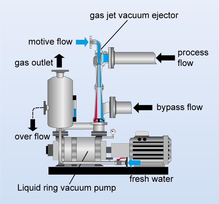
From the outside, the NASH vacuum pump only hints at how it's internal parts function. Shaft bearings on heavy cast iron brackets are easily accessible for servicing. The top connection of the pump is the inlet, while the side connection is its discharge some NASH pumps do have a different orientation. The NASH liquid ring vacuum pump uses water or any other suitable liquid, which acts as "liquid pistons", hence the name liquid ring. It's apparent that the chambers between the rotor blades, shown here in yellow, are open around the periphery.

The chambers are open on the inside, as well. These inner edges of the rotor blades are machined to rotate around the cone surface, shown in red , with a close non-contact fit. An internal passage joins the openings from the pump inlet to an inlet port in the cone. There's also a passage from the cone discharge to the discharge connection on the head. Some NASH pumps have a port plate configuration rather than conical, but the principle is the same. This diagram demonstrates what the rotor and body do while the pump is in operation.

The spinning of blue liquid forms a ring due to centrifugal force. Because the rotor axis and body axis are offset from each other, the liquid ring is not concentric with the rotor. Air or gas traverses the internal passage to the cone inlet port. As the white dots indicate, the gas is drawn into the rotor chambers by the receding liquid ring, similar to the suction stroke of a piston in a cylinder. The liquid ring does the job of pistons, while the rotor chambers play the part of cylinders.

As each chamber rotates past the inlet port, the chamber carries a volume of air or gas around with it. The white dots are confined between the cone and the ring of rotating liquid. The gas is compressed as the liquid ring converges with the cone. This represents the compression of air or gas from vacuum up to atmospheric pressure, or from atmospheric up to positive pressure in a liquid ring compressor.

When each chamber rotates to the discharge port opening, the compressed air or gas escapes from that chamber through the discharge port to the internal discharge passage. Air or gas, with the dots closely packed to indicate higher pressure, is shown here flowing out of the discharge connection at right. The flow is continuous without pulsation.

In this completed schematic, the entire vacuum pumping cycle is shown. Here air or gas entering the NASH pump is shown as white dots at the inlet connection. This represents the compression of air or gas from vacuum up to atmospheric pressure, or from atmospheric up to positive pressure in a liquid ring compressor Discharge 9. Learn more about the liquid ring principle from Nash, the original liquid ring innovator.