4 bit ripple carry adder circuit layout
This kind of circuit is most notably used in multipliers, which is why these circuits are also known as Dadda and Wallace multipliers. The circuit produces a two-bit output. By using this site, you agree to the Terms of Use and Privacy Policy. Some other multi-bit adder architectures break the adder into blocks.

Using only two types of gates is convenient if the circuit is being implemented using simple IC chips which contain only one gate type per chip. A full adder can be implemented in many different ways such as with a custom transistor -level circuit or composed of other gates. It is possible to vary the length of these blocks based on the propagation delay of the circuits to optimize computation time. It has two outputs, sum S and carry C.
A one-bit full-adder adds three one-bit numbers, often written as ABand C in ; A and 4 bit ripple carry adder circuit layout are the operands, and C in is a bit carried in from the previous less-significant stage. They work by creating two signals P and G for each bit position, based on whether a carry is propagated through from a less significant bit position at least one input is a 1generated 4 bit ripple carry adder circuit layout that bit position both inputs are 1or killed in that bit position both inputs are 0. The sum and the carry may be fed into two inputs of the subsequent 3-number adder without having to wait for propagation of a carry signal. By combining multiple carry-lookahead adders, even larger adders can be created. The input variables of a half adder are called the augend and addend bits.
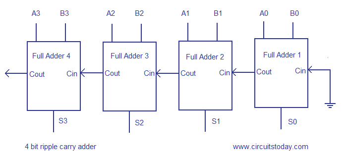
It is possible to create a logical circuit using multiple full adders to add N -bit numbers. The half adder adds two single binary digits A and B. By using this site, you agree to 4 bit ripple carry adder circuit layout Terms of Use and Privacy Policy. If an adding circuit is to compute the sum of three or more numbers, it can be advantageous to not propagate the carry result. This kind of adder is called a ripple-carry adder RCAsince each carry bit "ripples" to the next full adder.

The carry-in must travel through n XOR-gates in adders and n carry-generator blocks to have an effect on the carry-out. The half adder adds two single binary digits A and B. The input variables of a half adder 4 bit ripple carry adder circuit layout called the augend and addend bits. Using only two types of gates is convenient if the circuit is being implemented using simple IC chips which contain only one gate type per chip.
If an adding circuit is to compute the sum of three or more numbers, it can be advantageous to not propagate the carry result. Other signed number representations require more logic around the basic adder. An adder is a digital circuit that performs addition of numbers.